Week 6 - Wireless Sensor Network ft. XBee
- Nov 23, 2016
- 6 min read
Hi READERS,
So today in week 6, we learnt about wireless sensor network.
A wireless sensor network (WSN) are spatially distributed autonomous sensor to monitor physical environment conditions, such as temperature, sound, pressure, etc. and to cooperatively pass their data through the network to a main location.
There's many type of network topology but the one we learned are the following three:

Factors that affect Wireless Signal Network (WSN)
1. Distance
2. Power Consumption
3. Frequency
4. Protocol
5. Topology
6. Environment
7. Antenna
For today's activity, we will be using the XCTU Program to control the XBee.
Facts about the XBee:
It costs about 40 SGD !!!!
Low data rate (250kbit/s)
Low power consumption
Able to make mesh type sensor network
Can be connected to each other
Better security
If you're wondering if it can be transmitted through water,
IT CANT !!!!
Lets head into today's activity!
Today's activity is about introducing to us the way of wireless connection through the XBee and explain how the co-coordinator is responsible to poll for data from each node so that it doesn't congest the network.
Things requires for this week activity:
1) Laptop which have already install the XCTU program
2) XBee Module
3) XBee Explorer Dongle
4) Arduino
5) Jumper Wires
6) Buzzer
7) Sensor
Activity 1
In order to configure the XBee, we are required to attach it to the XBee Explore Dongle.
Note: Follow the direction and white colour to slot in the XBee Unit on red XBee Explore
Dongle.
( Red Board )

By using the XCTU Program, we can obtain the XBee:
Pan ID
Serial Number High
Serial Number Low
We also use the XCTU Program to Key In the destination address of our targeted XBee. We made 1 of our XBee to the PC Node (transmitting) and the END Node (receiving) for configuration to allow them to connect together.
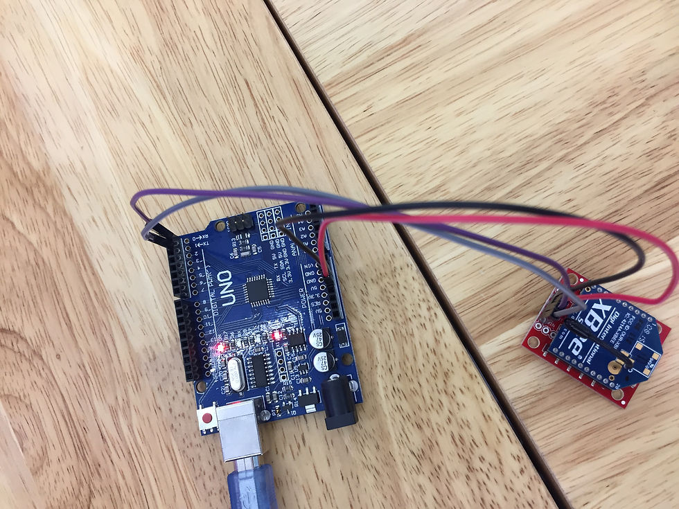
We connect the circuit as shown below.

Connection:
GND ---> GND
VCC ---> 5V
RX, Pin 0 ---> DOut
Tx, Pin 1 --- > DIn
We also uploaded the following code
//////////////////////////////////////////////////////////////////
//©2011 bildr
//Released under the MIT License - Please reuse change and share
//Monitors the serial port to see if there is data available.
//'a' turns on the LED on pin 13. 'b' turns it off.
//////////////////////////////////////////////////////////////////
void setup() { Serial.begin(9600); //initialize serial
pinMode(13, OUTPUT); //set pin 13 as output }
void loop() {
while(Serial.available()){ //is there anything to read?
char getData = Serial.read(); //if yes, read it
if(getData == 'a'){
digitalWrite(13, HIGH);
}else if(getData == 'b'){
digitalWrite(13, LOW);
}
}
}
This codes allows us to send data from the computer to the Arduino Wireless which will control the LED of the Arduino.
Send a ---> Turn off LED
Send b ---> Turn on LED
Note* : Never upload the Arduino code when the XBee Module is connected, you have to first remove the Din and Dout pin, if not there'll be error uploading the code
Activity 2 - You can ring my BELL.
We were partnered with group 4 to complete this activity.
This activity allow us to communicate with the other group through the XBee.
There's a switch circuit and a buzzer circuit to choose for this activity.
Our group decided to work on the buzzer circuit as show follow.
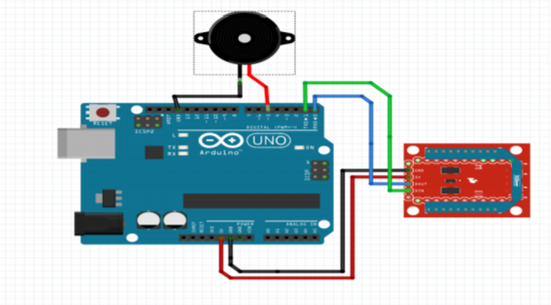
The Buzzer Circuit
Since we needed to communicate with the other group XBee, we went to exchange our END Node SH and SL (Serial number high and low).
We then, reconfigured our PC's Node DH(Destination Address High) and DL(Destination Address Low) code to the other group END Node.

After confiquring, we uploaded the following code.
int BELL = 5 ;
void setup ( ) {
pinMode (BELL, OUTPUT) ;
Serial.begin(9600);
}
void loop ( ) { // look for a capital D over the serial port and ring the bell if found
if (Serial.available() > 0 ) {
if (Serial.read () == ’D’ ) {
// ring the bell briefly
analogWrite (BELL,180 ) ; // ranging from 0−255
delay (10) ; analogWrite (BELL, 0 ) ;
}
}
}
After uploading the code given by our lecturer, there was some error
from the code. After consulting with the lecturer, we realize that at line 7
"if (Serial.read () == ’D’ )" the ’D’ should be written as 'D' .
Everything went smoothly after that.
This video shows that the person from the other group can "ring" our buzzer and vice-versa.
Activity 3
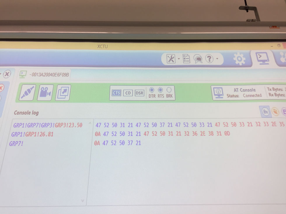
We are suppose to connect to our coordinator node to display it on the Projector for live graphing and analysis.
We then uploaded the coordinator code into our END Node, which will allow our XBee to be connected to the coordinator XBee.
We are suppose to transmit the data of our Week 1 Sensor by using the XBee.
Hence, Natalie added the following code into our initial program and edited it.
String inputString = ""; // a string to hold incoming data boolean stringComplete = false; // whether the string is complete String myCode = "GRPX!"; //Enter your group number in X void setup() { // initialize serial communications at 9600 bps: Serial.begin(9600); // reserve 200 bytes for the inputString: inputString.reserve(200); } void loop() { //call the function serialEvent(); // print the string when a newline arrives: if (stringComplete ) { if(inputString==myCode) { // print the results to the serial Serial.print("GRPX!" ); // Enter your group number in X Serial.println(YOUR SENSOR VALUE); // Replace YOUR SENSOR VALUE with your sensor data variable
The final code that sends our temperature data to the coordinator.
int DS18S20_Pin = 2; //DS18S20 Signal pin on digital 2 int Buzz = 13; int threshold = 32 ; String inputString = "Temperature"; // a string to hold incoming data boolean stringComplete = false; // whether the string is complete String myCode = "GRP1"; //Enter your group number in X
OneWire ds(DS18S20_Pin); // on digital pin 2 LiquidCrystal lcd(8, 9, 4, 5, 6, 7); void setup(void) { Serial.begin(9600); inputString.reserve(200); // set up the LCD's number of columns and rows: lcd.begin(16, 2); // Print a message to the LCD. lcd.print("Temperature:"); pinMode(Buzz, OUTPUT); }
void loop() { float temperature = getTemp() ;//will take about 750ms to run int Buz = temperature; // set the cursor to column 0, line 1 // (note: line 1 is the second row, since counting begins with 0): lcd.setCursor(0, 1); lcd.print("Celcius"); // print the number of seconds since reset: lcd.setCursor(9, 1); lcd.print(temperature); if (Buz >= threshold) { digitalWrite(Buzz, HIGH); } else { digitalWrite(Buzz, LOW); } //Serial.println(Buz); //Serial.println(threshold);
// Serial.println(temperature); //call the function serialEvent(); // print the string when a newline arrives: if (stringComplete ) { if(inputString==myCode) { // print the results to the serial Serial.print("GRP1!" ); // Enter your group number in X Serial.println(temperature); //Serial.println(Buz); // Serial.println(threshold);; // Replace YOUR SENSOR VALUE with your sensor data variable delay(1); } //else Serial.println("xxxx"); // clear the string: inputString = ""; stringComplete = false; } //delay(100); }
float getTemp(){ //returns the temperature from one DS18S20 in DEG Celsius
byte data[12]; byte addr[8];
if ( !ds.search(addr)) { //no more sensors on chain, reset search ds.reset_search(); return -1000; }
if ( OneWire::crc8( addr, 7) != addr[7]) { Serial.println("CRC is not valid!"); return -1000; }
if ( addr[0] != 0x10 && addr[0] != 0x28) { Serial.print("Device is not recognized"); return -1000; }
ds.reset(); ds.select(addr); ds.write(0x44,1); // start conversion, with parasite power on at the end delay(750); // Wait for temperature conversion to complete
byte present = ds.reset(); ds.select(addr); ds.write(0xBE); // Read Scratchpad
for (int i = 0; i < 9; i++) { // we need 9 bytes data[i] = ds.read(); } ds.reset_search(); byte MSB = data[1]; byte LSB = data[0];
float tempRead = ((MSB << 8) | LSB); //using two's compliment float TemperatureSum = tempRead / 16; return TemperatureSum; } void serialEvent() { while (Serial.available()) { // get the new byte: char inChar = (char)Serial.read(); // so the main loop can do something about it: if (inChar == '!') { stringComplete = true; } // else add it to the inputString: else inputString += inChar; } }
Problems Faced
The problem we faced while doing the final code is that there's a lot of serial print throughout our code which caused spamming of data to our coordinator.
This was solved by simple canceling out the serial print line.
All in all, today lesson is very fruitful as we have new exposure to a new type of electronics to communicate as we can't afford the XBee Module.
The XBee could be used in our project by transmitting data to our PC wireless without opening up our sensor box, which will give a much convenient way to obtain data and it could also help us controlling the parts that are controlled by the Arduino from outside.
Reflection
Phew... We finally finished all of today's activity.
As I ponder upon today's activity, I realised that even though we are not the best at what we do, we can overcome our problems together if we all work together.
Why do I say this?
In the beginning of today's activity, it was very confusing as we were trying to understand the instruction, we had different interpretations of the instructions. This caused a little misunderstanding but as we listened to each other, we were able to spot our mistakes and realise who was giving the right interpretation of the instruction.
Through this, we were able to complete today's activity in a nifty and I'm glad that we have each others back to count on for our project coming up ahead.
Thanks for reading :)
Written by: Kuan Ming


Comments